Fluid Catalytic Cracking (FCC) – Application Overview
An FCC is used to convert low value gas oils to valuable products like naphtha and diesel and slurry oil. It increases the hydrocarbon ratio by carbon rejection in a continuous process. In this process, a hot “fluid” catalyst at 538°C cracks heavy gas oil feed into gas/LPG, FCC petrol, light cycle oil, slurry oil and coke. The process converts straight-run atmospheric gas oils, vacuum gas oils, certain atmospheric residues and heavy stocks recovered from other refinery operations into high-octane petrol, light fuel oils and olefin-rich light gases such as propylene.
The FCC unit is comprised of three major parts (reaction, regenerator and combustion sections) and is considered the “heart” of the modern refinery. Major fuels conversions (gasoline) are produced out of the FCC. These units are straight run typically 36 or 48 months with fluidized bed catalytic reaction with AVGO or hydrocracker routed feed stock for low sulfur diesel and high octane gasoline production,light fuel oils and olefin rich light gases such as propylene with FCC a hot ‘fluid’ catalyst at 1000°F (538°C) cracks heavy gas oil feed. (Note: if feedstock not from the hydrocrackers then the end products are hydrotreated to meet ultra low sulfur specifications.)
PRIMARY PROCESS TECHNIQUE: Catalystic cracking increases H/C ratio by carbon rejection in a continuous process
PROCESS STEPS:
- Gas oil feed is dispersed into the bottom of a riser using steam
- Thermal cracking occurs on the surface if the catalyst
- Disengaging drum separates spent catalyst from products vapors
- Steam strips residue hydrocarbons from spent catalyst
- Air burns away the carbon film from the catalyst in either a partial burn or full burn mode operation.
- Regenerated catalyst enters bottom of riser – reactor
KEY PRODUCTS:
- High octane gasoline, propylene, butylene, LPG, kerosene, jet fuel, naphtha, slurry oil
- Lighter olefins and aromatics
- Low coke production as burned in regenerator with heat for cracking reactions
- Slurry – later routed to hydrocracker or blended into coker feed
- CO2 produced helps in steam for utilities
KEY APPLICATIONS:
- Feed pump isolation valves
- Frac bottoms pump isolation valves
- Frac recirculation
- Compressor suction 1st and 2nd stage isolation valves
- Catalyst handling valves (spent catalyst withdrawal, catalyst sampling, catalyst addition, catalyst fines block valves)
- TSS FSS separator isolation valves
- Pump around valves
- Slurry loop valves
KEY CHALLENGES FOR VALVES:
- High-temperature, thermal shock (760 -1400°F)
- Low pressure (30~60 PSI)
- High erosion in catalyst lines, maintain zero-leakage with positive isolation from each section as the catalyst are very expensive and a reliable zero-leakage valve helps in minimizing catalyst replacement
- Acidic corrosion
- Reliable longer operational valves for dependable isolation
- Zero-leakage in all operating conditions as well as low fugitive emission
- Fire safe and certified
BENEFITS OF A VALVTECHNOLOGIES’ PRODUCT: Integral seat design, zero-leakage at all operating conditions, purging to extend life of the equipment and also plant available. Fire safe and certified, in-house RiTech® coating technology.
TOTAL COST-OF-OWNERSHIP: Five years and above operation, customer can upgrade trims and coating and document it for the next run saving up a lot time and money.
| DIFFERENTIATING FEATURES | |
Integral seat
| |
Highest spring strength in the category
| |
Coatings/seating surface
|
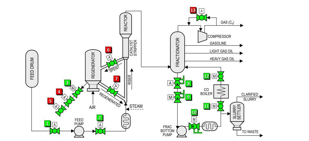
| FLOW DIAGRAM | |||||
| Item | Applications | Temp range (°F) | Pressure (psi) | Size (in) | |
| 1 | Feed drum emergency block valve | 200 – 300 | 50 | 6 – 12 | |
| 2 | Feed isolation | 200 – 300 | 100 | 6 – 10 | |
| 3 | Spent catalyst withdrawal root isolation | 800 – 1425 | 30 | 2 – 8 | |
| 4 | Spent catalyst withdrawal block valve | 800 – 1425 | 30 | 2 – 8 | |
| 5 | Throttling spent catalyst withdrawal valve | 800 – 1425 | 30 | 2 – 8 | |
| 6 | Catalyst regenerator inlet | 800 – 1425 | 30 | 2 – 8 | |
| 7 | Catalyst regenerator outlet | 800 – 1425 | 30 | 2 – 8 | |
| 8 | Frac bottoms emergency block valve | 500 – 850 | 30 | 8 – 20 | |
| 9 | Frac tower bottoms filter isolation | 500 – 850 | 150 | 6 – 12 | |
| 10 | Frac bottoms exchange isolation | 500 – 850 | 150 | 4 – 10 | |
| 11 | CO boiler inlet isolation | 500 – 850 | 150 | 4 – 10 | |
| 12 | CO boiler outlet isolation | 500 – 850 | 150 | 4 – 10 | |
| 13 | Wet gas compressor surge control valve | 100 – 200 | 30 – 200 | 10 – 20 | |
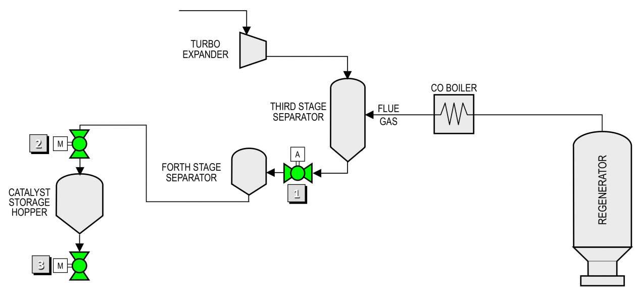 | |||||
| Item | Applications | Temp range (°F) | Pressure (psi) | Size (in) | |
| 1 | Third stage separator isolation | 800 – 1425 | 30 | 4 – 10 | |
| 2 | Fourth stage separator isolation | 500 – 1000 | 30 | 6 – 12 | |
| 3 | Spent catalyst storage hopper isolation | 200 – 500 | ATM | 4 – 10 | |