product

HPAL & POx Autoclave Valves

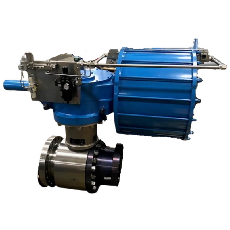
POx autoclave‑rated ball valve close‑up

HPAL & POx Autoclave Valves

The mining industry poses some of the most challenging of all severe service applications.

The most difficult of these challenges are high pressure acid leaching (HPAL) and pressure oxidation (POx). These applications require experience, reliability and resistance to high-temperatures, high-pressures and abrasive/corrosive slurries.

Hydrometallurgy Technologies Using Autoclaves

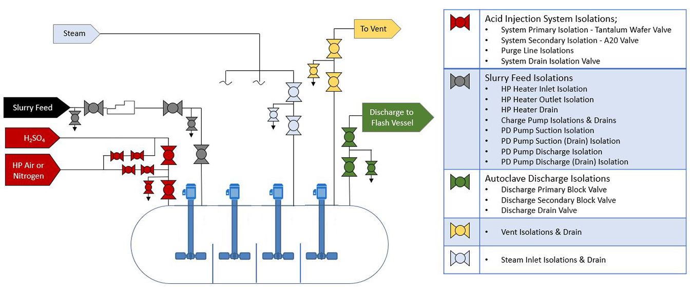
High Pressure Acid Leach – HPAL – ValvTechnologies’ Valve ApplicationsCutaway view of HPAL process ball valve internals
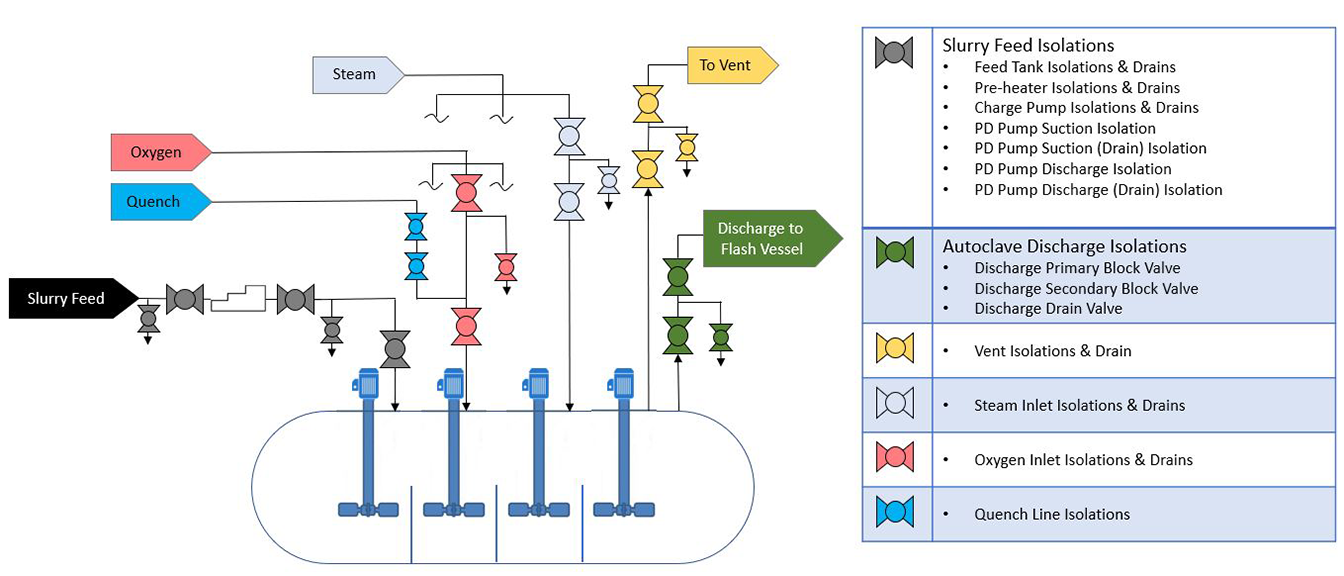
Pressure Oxidization– POx – ValvTechnologies’ Valve ApplicationsHPAL autoclave valve installed on processing line
FAQs – Autoclave Valves

Which materials are used for constructing these valves?

Abrasoblock® autoclave valves are built with titanium Grade 12, duplex stainless steel, and other exotic alloys designed for high-temperature, corrosive, and abrasive environments.

Our HPAL & POX autoclave valves meet rigorous industry requirements: all pressure-containing parts are ultrasonically tested; body and seats undergo pressure testing per A-TQP-010; and fabrication adheres to ASME Section II and PED standards. Additionally, they achieve zero-leakage under API 6D Appendix C testing.

POx autoclave‑rated ball valve close‑up

Looking for more help with
HPAL & POx Autoclave Valves?

Ask the experts in valves,
ValvTechnologies is ready to help.

product

Electronic Relief Valve

Electronic Relief Valve
Electronic relief valve close‑up image
Click Image to Enlarge
Technical Data
Sizes
2 1/2” x 4” and larger
Pressure Classes

ASME / ANSI class up to 4500

Materials of Construction

Carbon steel (A105, A216 WCB) – standard
Alloy steel (F22, F91, A217 WC9, A217 C12A) – standard
Stainless steel (316H, A351 CF8M) – standard
Duplex steel exotic alloys
Other materials available upon request

In Compliance

ASME B16.34
PED
Nuclear ASME III Class 1, 2 and 3
Nuclear Safety Related – 10CFR50 Appendix B
SIL

End Connections

Buttweld – standard
Raised-face flange – standard
Other end connections available upon request

Shutoff

Repeatable tight shut-off

Electronic Relief Valve

Pilot Operated Relief

Valv - ERV

Consider the safety rating, productivity value and cost savings of electronic relief valves – the relief valve whose standard blowdown and set pressure is accurate to 0.1% of 1 psi. ValvTechnologies’ ERV is the perfect combination of zero-leakage isolation valve plus the electronic controls needed to monitor and regulate system pressures in a safety valve environment and within ASME Code Section I “V” Stamp requirements where critical over-pressure protection is paramount. ValvTechnologies’ ERV is the benchmark.

Electronic relief valve close‑up image

ValvTechnologies’ zero-leakage ERV valves are commonly supplied with the following items:

  • ValvTechnologies’ zero-leakage, V Series valve
  • Actuator – options include: air, spring, hydraulic, D.C. electric, A.C. electric, fail-safe last position, fail-safe (pneumatic tank or spring return)
  • Pressure transducer
  • Weatherproof control box
  • DCS signal input

Additional options are also available, including:

  • Remote panel
  • Lockable switch
  • Drip pans / exhaust pans
  • Voltages
  • Silencers
  • Heaters
Valve actuator mounted on electronic relief valve
Technical Data
Sizes
2 1/2” x 4” and larger
Pressure Classes

ASME / ANSI class up to 4500

Materials of Construction

Carbon steel (A105, A216 WCB) – standard
Alloy steel (F22, F91, A217 WC9, A217 C12A) – standard
Stainless steel (316H, A351 CF8M) – standard
Duplex steel exotic alloys
Other materials available upon request

In Compliance

ASME B16.34
PED
Nuclear ASME III Class 1, 2 and 3
Nuclear Safety Related – 10CFR50 Appendix B
SIL

End Connections

Buttweld – standard
Raised-face flange – standard
Other end connections available upon request

Shutoff

Repeatable tight shut-off

ValvTechnologies’ ERV fulfills the need for a zero-leakage, pilot-operated relief valve. The ERV package combines ValvTechnologies’ zero-leakage isolation valve with electronic controls to monitor and regulate system pressure. Whether in a capacity relieving function requiring the ASME V-Stamp or simply an overpressure protection application, the ERV provides reliable protection for standard safety valves in many industries. ValvTechnologies can also provide an integral isolation valve, eliminating the need for costly field welding.  Standard blowdown and set pressure is accurate to 1/1000.

  1. Integral metal seat.With our patented HVOF RiTech® coating process, the integral seat in ValvTechnologies’ rotary operating valves are resistant from the attack of abrasive magnetite or ferrous oxides in the steam flow.
  2. Body seal ring. ValvTechnologies employs a field proven seal ring technology to ensure sealing under all operating conditions, up to 1400°F. The body seal ring is loaded at a pressure higher than 20,000 psi. In addition, valves sized three inch and above contain a secondary Grafoil seal to further guarantee reliability
  3. Patented coating process. The sealing surfaces are overlaid with tungsten or chromium carbide using our exclusive HVOF RiTech® process. These surfaces have a hardness of 68 – 72 Rc to allow long periods of operation in the most severe conditions.
  4. Live-loaded gland area. The V Series gland packing design features a four stud, live-loaded assembly designed for heavy industrial applications. The packing material is high purity Grafoil® surrounded by carbon fiber / Inconel anti-extrusion rings. The six Bellville springs (per stud) provide constant load pressure through extreme thermal shocks and prevent wear leaks in high cycle service.
  5. Blow-out proof stem design utilizes a one piece, hard-faced, blow-out proof stem that is inserted through the inside of the body cavity eliminating the possibility of blow-out through the gland area.
  6. End cap. ValvTechnologies design utilizes a end cap with a diffuser outlet with optional end connections.

  • Tight shut-off: As a standard, ValvTechnologies meets zero-leakage requirements on low-pressure air and high-pressure water
  • High spring load: ValvTechnologies’ very high spring load not only assures contact between the ball and seat, but at all positions from open to close
  • Accuracy to 1/10% of 1 PSI: Pinpointed opening pressure
  • High-precision reliability: Consistent reliable operation
  • Low maintenance requirements: Low cost-of-ownership
  • Accurate blow-downs: Major cost savings
  • Seat out-of-flow path when open: Unimpeded flow path with no impingement
  • Easily adapted to existing controls: Potential cost-saving when adaptable to existing controls
  • Various standard control packages: Highly customizable
  • Integral isolation valves available: Two valves in one for easy installation
  • Full pressure protection: Maximizes over pressure protection
  • Easily adjusted high and low set points: Ease if installation set up
  • Secondary pressure signals can be taken from the boiler nozzle or any other source – customer’s choice: Installation flexibility
  • Multiple signals can be prioritized: Operational flexibility
  • Standard controls can be adapted to customer requirements: Installation flexibility
  • DCS signal interfaces available as dry and wet contacts: User-friendly adaptability

Z Series ERV – Premium Package ; Standard with a control box, complete fast-acting actuation package, longer diffuser discharge piping which minimizes noise and maximizes flow.

  • Set points – The set points of the “Z” series ERV are ± 0.1% accuracy. This accuracy results in less steam loss during an actuation/cycle and better protection of the drum and superheat conventional safety valves.
  • Safety – The take off point for the signal will typically be from the drum or superheater. This live steam point must then be cooled to prevent overheating of the pressure transmitter. To ensure safe maintenance and operations, ValvTechnologies has designed a system which consists of a coiled P22 piped siphon which is then welded to a Monel diaphragm seal. The outlet of the Monel diaphragm seal is then connected to the miniature cooling tower and the piezoresistive transmitter. As the diaphragm seal is a pressure boundary the transmitter may be removed without breaking into the pressure boundary.
  • Diffuser outlet – The diffuser must be piped to a discharge drip pan for reliable and safe operation. Hard piping to a header or silencer is strictly forbidden.
  • Controls – The standard control unit, in addition to lights, push buttons and selector switch, will also have a programmable controller to allow easy adjustments of blow-down. It also includes an actuation/cycle counter and a local pressure indication display.
  • Optional isolation valve – Combination valve package for non-ASME Code Section I V stamped applications for two valves in one assembly eliminating a critical weld during installation. ASME Code Section I V stamped applications require a minimum of two ERVs for redundancy purposes.

R Series ERV – Economical Package – Standard product with a shorter diffuser discharge, without the fast-acting actuation package and control box. As with the Z Series, the discharge must be piped to a drip pan for safe reliable operation.

  • Set point – Accurate to 0.25% with pressure transducer that customer connects to a pressure sensing line. The line requires an isolation device.
  • Standard actuation – High temperature pneumatic actuator with solenoids and limit switch that contains relevant terminals
  • Terminal box – for connections from the control room
  • Optional – Siphon and control box
  • Optional isolation valve – See explanation above

Our Promise | Absolute Zero-leakage

The ValvTechnologies ERV for use in main steam relief system is a vital contributer toward the safe and reliable operation of a power plant. It is not to be used as a start up / sky vent. Utilizing this product in that capacity voids any warranty, expressed or implied.

Seller warrants the equipment of its own manufacture to be free of defects in material and workmanship. The equipment must be installed utilizing manufacturer’s recommended installation instructions, incorporating industry guidelines, and proper use of the equipment for its intended safety function during normal plant operations, for a period of four years from date of shipment from Seller’s plant. Seller’s obligation under this warranty shall be strictly limited, at Seller’s option, to: (i) furnishing replacement parts for, or repairing without charge to Purchaser, F.O.B. Houston, Texas; or (ii) repair, without charge to Purchaser, at costs comparable to Seller’s normal manufacturing costs, those parts proven defective; or (iii) in discharge of Seller’s maximum liability herewith, refunding all monies paid by Purchaser to Seller for the product and, at discretion of Seller, having the product transportation charges relative to corrective work, defective parts or replacement parts shall be born by Purchaser. Purchaser shall give Seller immediate notice upon discovery of any defect.

The undertaking of unauthorized repairs or replacement by Purchaser or its agents or any alteration in material or design of the Seller’s product, components or parts thereof by any party other than a ValvTechnologies authorized representative shall void all obligations of Seller regarding the product and any associated warranty herein stated or implied and shall relieve Seller of all responsibility herewith.

Finished materials and accessories purchased from other manufacturers, whether attached to manufactured product of the Seller or not, are warranted only to the extent of manufacturer’s warranty to Seller. Warranty responsibility for the entire valve and actuator assembly shall be assumed by the company selecting and/or mounting an operating device on a bare stem valve. Seller has the sole discretion to determine if an automated bare stem valve shall be within Seller’s warranty obligation. Further, the full or partial removal, tampering or alteration of the actuation system, parts or components by any party other than a ValvTechnologies’ authorized representative shall void all obligations of Seller regarding the product and any associated warranty herein stated or implied.

Seller’s sole liability shall be exclusively as set forth herein, and Seller shall not be liable for any incidental or consequential damages due to its breach of any warranty herein contained, or otherwise. Without limitation to the foregoing, in no event shall Seller be liable for the loss of use of the product, or for the loss of use of any other product, process, plant, equipment, or facilities of the Purchaser or the end-user whether partially or wholly due to defects in material and/or design of Seller’s product; and in no event shall Seller be liable for removal of appurtenances or incidentals such as connections, pipe work and similar items of obstruction or for any cost brought about by the necessity of removing the product from its point of installation.

Seller makes no warranty of any kind whatsoever, express or implied, other than as specifically stated herein; and there are no warranties of merchantability and/or fitness for a particular purpose which exceed the obligations and warranties specifically stated herein.

Parts furnished without charge as replacements for original parts under warranty are warranted for that period of time during which the original parts warranty is effective.

FOUR-YEAR, ZERO-LEAKAGE GUARANTEE

FAQs – Electronic Relief Valves

What is a Zero-Leakage Electronic Relief Valve (ERV) by ValvTechnologies?

ValvTechnologies’ Electronic Relief Valve, ERV, combines a zero-leakage, metal-seated V Series isolation valve with advanced electronic controls for real-time system pressure monitoring and regulation. It’s certified under ASME Section I “V” Stamp, ensuring precise overpressure protection in critical applications.

Electronic Relief Valves offer exceptional precision: blowdown and set point accuracy up to 1% of 1 psi (or 1/1000 precision), enabling substantial cost and energy savings.

Standard materials include carbon steel (A105, A216 WCB), alloy steels (F22, F91, A217 WC9, A217 C12A), and stainless steels (316H, A351 CF8M). Duplex and exotic alloys are available upon request for more severe environments.

ERV valves can be equipped with various actuators: pneumatic (single or double-acting), hydraulic, DC or AC electric, or fail-safe options (spring return or pneumatic tank). Standard supplies also include a pressure transducer, NEMA 4X stainless steel control box, and DCS-ready I/O capabilities. Additional options such as remote panels, lockable switches, drip pans, silencers, and heaters are available.

ERVs can integrate an optional isolation valve, enabling removal or servicing without field welding. Blowdown and set points are programmable, and the system supports tight shut-off, reducing steam loss and improving system efficiency.

Routine maintenance includes inspecting the stem/gland for leaks and verifying body bolt tightness. Periodically cycling the valve ensures proper 90° rotation. The live-loaded packing system minimizes adjustments, with guidelines provided for safe torque application when required.

Electronic relief valve close‑up image

Looking for more help with
Electronic Relief Valve?

Ask the experts in valves,
ValvTechnologies is ready to help.

ValvTechnologies’ ERV fulfills the need for a zero-leakage, pilot-operated relief valve. The ERV package combines ValvTechnologies’ zero-leakage isolation valve with electronic controls to monitor and regulate system pressure. Whether in a capacity relieving function requiring the ASME V-Stamp or simply an overpressure protection application, the ERV provides reliable protection for standard safety valves in many industries. ValvTechnologies can also provide an integral isolation valve, eliminating the need for costly field welding.  Standard blowdown and set pressure is accurate to 1/1000.

  1. Integral metal seat.With our patented HVOF RiTech® coating process, the integral seat in ValvTechnologies’ rotary operating valves are resistant from the attack of abrasive magnetite or ferrous oxides in the steam flow.
  2. Body seal ring. ValvTechnologies employs a field proven seal ring technology to ensure sealing under all operating conditions, up to 1400°F. The body seal ring is loaded at a pressure higher than 20,000 psi. In addition, valves sized three inch and above contain a secondary Grafoil seal to further guarantee reliability
  3. Patented coating process. The sealing surfaces are overlaid with tungsten or chromium carbide using our exclusive HVOF RiTech® process. These surfaces have a hardness of 68 – 72 Rc to allow long periods of operation in the most severe conditions.
  4. Live-loaded gland area. The V Series gland packing design features a four stud, live-loaded assembly designed for heavy industrial applications. The packing material is high purity Grafoil® surrounded by carbon fiber / Inconel anti-extrusion rings. The six Bellville springs (per stud) provide constant load pressure through extreme thermal shocks and prevent wear leaks in high cycle service.
  5. Blow-out proof stem design utilizes a one piece, hard-faced, blow-out proof stem that is inserted through the inside of the body cavity eliminating the possibility of blow-out through the gland area.
  6. End cap. ValvTechnologies design utilizes a end cap with a diffuser outlet with optional end connections.

  • Tight shut-off: As a standard, ValvTechnologies meets zero-leakage requirements on low-pressure air and high-pressure water
  • High spring load: ValvTechnologies’ very high spring load not only assures contact between the ball and seat, but at all positions from open to close
  • Accuracy to 1/10% of 1 PSI: Pinpointed opening pressure
  • High-precision reliability: Consistent reliable operation
  • Low maintenance requirements: Low cost-of-ownership
  • Accurate blow-downs: Major cost savings
  • Seat out-of-flow path when open: Unimpeded flow path with no impingement
  • Easily adapted to existing controls: Potential cost-saving when adaptable to existing controls
  • Various standard control packages: Highly customizable
  • Integral isolation valves available: Two valves in one for easy installation
  • Full pressure protection: Maximizes over pressure protection
  • Easily adjusted high and low set points: Ease if installation set up
  • Secondary pressure signals can be taken from the boiler nozzle or any other source – customer’s choice: Installation flexibility
  • Multiple signals can be prioritized: Operational flexibility
  • Standard controls can be adapted to customer requirements: Installation flexibility
  • DCS signal interfaces available as dry and wet contacts: User-friendly adaptability

Z Series ERV – Premium Package ; Standard with a control box, complete fast-acting actuation package, longer diffuser discharge piping which minimizes noise and maximizes flow.

  • Set points – The set points of the “Z” series ERV are ± 0.1% accuracy. This accuracy results in less steam loss during an actuation/cycle and better protection of the drum and superheat conventional safety valves.
  • Safety – The take off point for the signal will typically be from the drum or superheater. This live steam point must then be cooled to prevent overheating of the pressure transmitter. To ensure safe maintenance and operations, ValvTechnologies has designed a system which consists of a coiled P22 piped siphon which is then welded to a Monel diaphragm seal. The outlet of the Monel diaphragm seal is then connected to the miniature cooling tower and the piezoresistive transmitter. As the diaphragm seal is a pressure boundary the transmitter may be removed without breaking into the pressure boundary.
  • Diffuser outlet – The diffuser must be piped to a discharge drip pan for reliable and safe operation. Hard piping to a header or silencer is strictly forbidden.
  • Controls – The standard control unit, in addition to lights, push buttons and selector switch, will also have a programmable controller to allow easy adjustments of blow-down. It also includes an actuation/cycle counter and a local pressure indication display.
  • Optional isolation valve – Combination valve package for non-ASME Code Section I V stamped applications for two valves in one assembly eliminating a critical weld during installation. ASME Code Section I V stamped applications require a minimum of two ERVs for redundancy purposes.

R Series ERV – Economical Package – Standard product with a shorter diffuser discharge, without the fast-acting actuation package and control box. As with the Z Series, the discharge must be piped to a drip pan for safe reliable operation.

  • Set point – Accurate to 0.25% with pressure transducer that customer connects to a pressure sensing line. The line requires an isolation device.
  • Standard actuation – High temperature pneumatic actuator with solenoids and limit switch that contains relevant terminals
  • Terminal box – for connections from the control room
  • Optional – Siphon and control box
  • Optional isolation valve – See explanation above

Our Promise | Absolute Zero-leakage

The ValvTechnologies ERV for use in main steam relief system is a vital contributer toward the safe and reliable operation of a power plant. It is not to be used as a start up / sky vent. Utilizing this product in that capacity voids any warranty, expressed or implied.

Seller warrants the equipment of its own manufacture to be free of defects in material and workmanship. The equipment must be installed utilizing manufacturer’s recommended installation instructions, incorporating industry guidelines, and proper use of the equipment for its intended safety function during normal plant operations, for a period of four years from date of shipment from Seller’s plant. Seller’s obligation under this warranty shall be strictly limited, at Seller’s option, to: (i) furnishing replacement parts for, or repairing without charge to Purchaser, F.O.B. Houston, Texas; or (ii) repair, without charge to Purchaser, at costs comparable to Seller’s normal manufacturing costs, those parts proven defective; or (iii) in discharge of Seller’s maximum liability herewith, refunding all monies paid by Purchaser to Seller for the product and, at discretion of Seller, having the product transportation charges relative to corrective work, defective parts or replacement parts shall be born by Purchaser. Purchaser shall give Seller immediate notice upon discovery of any defect.

The undertaking of unauthorized repairs or replacement by Purchaser or its agents or any alteration in material or design of the Seller’s product, components or parts thereof by any party other than a ValvTechnologies authorized representative shall void all obligations of Seller regarding the product and any associated warranty herein stated or implied and shall relieve Seller of all responsibility herewith.

Finished materials and accessories purchased from other manufacturers, whether attached to manufactured product of the Seller or not, are warranted only to the extent of manufacturer’s warranty to Seller. Warranty responsibility for the entire valve and actuator assembly shall be assumed by the company selecting and/or mounting an operating device on a bare stem valve. Seller has the sole discretion to determine if an automated bare stem valve shall be within Seller’s warranty obligation. Further, the full or partial removal, tampering or alteration of the actuation system, parts or components by any party other than a ValvTechnologies’ authorized representative shall void all obligations of Seller regarding the product and any associated warranty herein stated or implied.

Seller’s sole liability shall be exclusively as set forth herein, and Seller shall not be liable for any incidental or consequential damages due to its breach of any warranty herein contained, or otherwise. Without limitation to the foregoing, in no event shall Seller be liable for the loss of use of the product, or for the loss of use of any other product, process, plant, equipment, or facilities of the Purchaser or the end-user whether partially or wholly due to defects in material and/or design of Seller’s product; and in no event shall Seller be liable for removal of appurtenances or incidentals such as connections, pipe work and similar items of obstruction or for any cost brought about by the necessity of removing the product from its point of installation.

Seller makes no warranty of any kind whatsoever, express or implied, other than as specifically stated herein; and there are no warranties of merchantability and/or fitness for a particular purpose which exceed the obligations and warranties specifically stated herein.

Parts furnished without charge as replacements for original parts under warranty are warranted for that period of time during which the original parts warranty is effective.

FOUR-YEAR, ZERO-LEAKAGE GUARANTEE

product

Turbine Bypass Systems

Click Image to Enlarge
Technical Data
Sizes
4 – 24 “
Pressure Classes

ASME / ANSI Class 150 – 4500

Materials of Construction

Carbon steel (A105, A216 WCB) – standard
Alloy steel (F22, F91, A217 WC9, A217 C12A) – standard
Stainless steel (316H, A351 CF8M) – standard
Duplex steel
Exotic alloys
Other materials available upon request

In Compliance

B16.34 PED N & NPT – Nuclear Authorized

End Connections

Buttweld – standard
Raised-face flange – standard
Other end connections available upon request

Shutoff

Zero-leakage

Turbine Bypass Systems

IGCC - Ready and Able

Valv - VSeries

Now keep gas turbine and heat recovery system generator (HRSG) online in the event of a steam turbine trip with the ValvTechnologies’ turbine bypass system (TBS). Purposefully designed for the new generation of combined-cycle power plants, our TBS combines the proven XactrolL® severe service control valve design with a state-of-the-art de-superheating control system. At the same time, the TBS facilitates fast HRSG and CT start-ups in peaking power plants. and helps these plants operate at turndown conditions far below the levels that can be achieved with standard governor systems.

Turbine bypass

Looking for more help with
Turbine Bypass Systems?

Ask the experts in valves,
ValvTechnologies is ready to help.

  • Operation at turndown conditions far below levels that can be achieved with standard governor systems
  • Guaranteed zero-leakage performance delivers repeatable isolation and preserves operating integrity
  • Outstanding control in critical combined cycle operation improves system efficiency and productivity
  • Assured drum level control stability during a trip event and faster stream turbine re-starts via improved control system
  • High-quality performance created by experienced design and ISO 9001-certified manufacturing

Various control packages available integral isolation

product

Check Valves

DFT® non‑slam check valve close‑up
Click Image to Enlarge
Technical Data
Sizes
1/4 - 24“
Pressure Classes

ASME / ANSI Class 150 – 2500

In Compliance

ASME B16.34
PED
Nuclear ASME III Class 1, 2 and 3
Nuclear Safety Related – 10CFR50 Appendix B
SIL


Check Valves

ValvTechnologies / DFT® Nuclear Check Valves.

ValvTechnologies is an exclusive distributor of in-line check valves for nuclear applications and licensed manufacturer of ASME III and safety-related check valves.

Designed to prevent “water hammer”, the spring-assisted, in-line design featured in all DFT® check valves ensures that as the forward flow in a pipeline decreases, the disc begins moving closer to the seat. By the time the flow stops, the disc is closed against the seat, preventing flow reversal. This prevents the valve from slamming closed, causing “water hammer” and the resultant noise and damage to piping systems.

DFT® non‑slam check valve close‑up
Technical Data
Sizes
1/4 - 24“
Pressure Classes

ASME / ANSI Class 150 – 2500

In Compliance

ASME B16.34
PED
Nuclear ASME III Class 1, 2 and 3
Nuclear Safety Related – 10CFR50 Appendix B
SIL

  • Designed to prevent “water hammer.” The spring-assisted, axial flow, in-line, nozzle style, non-slam design featured in all DFT® check valves insures that as the forward flow in a pipeline decreases, the disc begins moving closer to the seat. By the time the flow stops, the disc is closed against the seat preventing flow reversal. This prevents the valve from slamming closed, which can cause “water hammer” and the resultant noise and damage to piping systems.
  • Designed to open at approx. 0.5 psi differential pressure and fully open at 1.0 psi differential pressure
  • Can be installed in ANY position. Including vertical with flow up or down (Special springs may be required.)
  • MSS SP 126-2000 Steel Non-slam Spring-Assisted Center Guided Check Valves Standard. DFT® carbon steel, stainless steel and alloy valves meet this standard
  • Meet or exceed MSS SP-61 leakage requirements. Metal-to-metal seating is standard in all DFT® non-slam check valves
  • Dual-guided stems. The stem is guided upstream and downstream in certain designs, to guard against vibrations and insure proper disc seating
  • Custom sizing available. The following DFT® check valves can be sized to the appropriate flow conditions: ALC®, Excalibur®, GLC®, WLC®, and Y-Calibur™
  • Pulse-damping design

The DFT® Model PDC® is specifically designed for use on the discharge of reciprocating air or gas compressors. The design includes a pulse-damping chamber to protect against premature seat wear due to chattering.

  • Liquids, gas or steam. All DFT® non-slam check valves provide positive shutoff for applications involving liquids, gas, or steam. Applications include chemical lines, fluid injection, condensate recovery, steam, nitrogen, pump, and compressor discharge, chiller and boiler feed systems.
  • Maintenance and Installation guides available for all DFT® non-slam check valves.

  • Designed to prevent “water hammer”
  • Spring assisted, in-line design ensures that as the forward flow decreases, the disc begins to move closer to the seat
  • Real flexibility in application, from 1/4 to 24 “ 150 – 2500# class

FAQs – Check Valves

How do check valves prevent water hammer and ensure smooth closing?

The spring-assisted axial flow design ensures the disc closes gradually as forward flow slows, positioning the disc against the seat just as flow stops. This soft-close action prevents slamming, reducing noise and protecting pipeline integrity.

  • Positive shutoff for liquids, gases, or steam.
  • Center- or dual-guided stems to reduce vibration and improve seating performance.
  • Pulse-damping design (PDC®) to reduce wear from flow oscillations.
DFT® non‑slam check valve close‑up

Looking for more help with
Check Valves?

Ask the experts in valves,
ValvTechnologies is ready to help.

  • Designed to prevent “water hammer.” The spring-assisted, axial flow, in-line, nozzle style, non-slam design featured in all DFT® check valves insures that as the forward flow in a pipeline decreases, the disc begins moving closer to the seat. By the time the flow stops, the disc is closed against the seat preventing flow reversal. This prevents the valve from slamming closed, which can cause “water hammer” and the resultant noise and damage to piping systems.
  • Designed to open at approx. 0.5 psi differential pressure and fully open at 1.0 psi differential pressure
  • Can be installed in ANY position. Including vertical with flow up or down (Special springs may be required.)
  • MSS SP 126-2000 Steel Non-slam Spring-Assisted Center Guided Check Valves Standard. DFT® carbon steel, stainless steel and alloy valves meet this standard
  • Meet or exceed MSS SP-61 leakage requirements. Metal-to-metal seating is standard in all DFT® non-slam check valves
  • Dual-guided stems. The stem is guided upstream and downstream in certain designs, to guard against vibrations and insure proper disc seating
  • Custom sizing available. The following DFT® check valves can be sized to the appropriate flow conditions: ALC®, Excalibur®, GLC®, WLC®, and Y-Calibur™
  • Pulse-damping design

The DFT® Model PDC® is specifically designed for use on the discharge of reciprocating air or gas compressors. The design includes a pulse-damping chamber to protect against premature seat wear due to chattering.

  • Liquids, gas or steam. All DFT® non-slam check valves provide positive shutoff for applications involving liquids, gas, or steam. Applications include chemical lines, fluid injection, condensate recovery, steam, nitrogen, pump, and compressor discharge, chiller and boiler feed systems.
  • Maintenance and Installation guides available for all DFT® non-slam check valves.

  • Designed to prevent “water hammer”
  • Spring assisted, in-line design ensures that as the forward flow decreases, the disc begins to move closer to the seat
  • Real flexibility in application, from 1/4 to 24 “ 150 – 2500# class

ValvTorque Automation

Actuation Solutions Built for Reliability, Precision, and Control

When performance matters most, your actuation system cannot be the weak link. Our actuator solutions are engineered to deliver precise, dependable valve operation in the most demanding applications.

Designed for seamless integration with ValvTechnologies’ zero-leakage valves, our actuators provide the torque, speed, and control needed to ensure consistent performance, extended service life, and reduced operational risk.

product

Coatings

DFT® non‑slam check valve close‑up
Click Image to Enlarge
Technical Data
Sizes
1/4 - 24“
Pressure Classes

ASME / ANSI Class 150 – 2500

In Compliance

ASME B16.34
PED
Nuclear ASME III Class 1, 2 and 3
Nuclear Safety Related – 10CFR50 Appendix B
SIL

Coatings

ValvTechnologies Advanced Coating Technology

Our advanced coating technology is befitting for our Zero Leakage metal-seated ball valves. Our cutting-edge coating processes enhance the performance and durability of our valves, making them ideal for even the most demanding applications (high temp, high corrosion, high abrasion, high pressure). 

The Advantages of Our Coatings Technology  

  • Enhanced Durability: Our coatings provide outstanding protection against wear, corrosion, and erosion, greatly extending the lifespan of our valves.  
  • Improved Performance: The low-friction surface reduces wear on internal components, ensuring smoother operation and better overall performance.  
  • Resistance to Harsh Environments: With excellent chemical resistance, our coatings, such as RiBlock AC 360, can withstand even the most corrosive environments, making our valves suitable for a wide range of applications.  
  • Reduced Maintenance Costs: By increasing valve longevity and minimizing wear and tear, our coatings helps companies save on maintenance and replacement costs over time.  

  • Designed to prevent “water hammer.” The spring-assisted, axial flow, in-line, nozzle style, non-slam design featured in all DFT® check valves insures that as the forward flow in a pipeline decreases, the disc begins moving closer to the seat. By the time the flow stops, the disc is closed against the seat preventing flow reversal. This prevents the valve from slamming closed, which can cause “water hammer” and the resultant noise and damage to piping systems.
  • Designed to open at approx. 0.5 psi differential pressure and fully open at 1.0 psi differential pressure
  • Can be installed in ANY position. Including vertical with flow up or down (Special springs may be required.)
  • MSS SP 126-2000 Steel Non-slam Spring-Assisted Center Guided Check Valves Standard. DFT® carbon steel, stainless steel and alloy valves meet this standard
  • Meet or exceed MSS SP-61 leakage requirements. Metal-to-metal seating is standard in all DFT® non-slam check valves
  • Dual-guided stems. The stem is guided upstream and downstream in certain designs, to guard against vibrations and insure proper disc seating
  • Custom sizing available. The following DFT® check valves can be sized to the appropriate flow conditions: ALC®, Excalibur®, GLC®, WLC®, and Y-Calibur™
  • Pulse-damping design

The DFT® Model PDC® is specifically designed for use on the discharge of reciprocating air or gas compressors. The design includes a pulse-damping chamber to protect against premature seat wear due to chattering.

  • Liquids, gas or steam. All DFT® non-slam check valves provide positive shutoff for applications involving liquids, gas, or steam. Applications include chemical lines, fluid injection, condensate recovery, steam, nitrogen, pump, and compressor discharge, chiller and boiler feed systems.
  • Maintenance and Installation guides available for all DFT® non-slam check valves.

  • Designed to prevent “water hammer”
  • Spring assisted, in-line design ensures that as the forward flow decreases, the disc begins to move closer to the seat
  • Real flexibility in application, from 1/4 to 24 “ 150 – 2500# class