H-oil – Ebulating Bed H-oil / LC Fining – Application Overview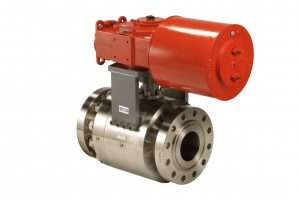
The heavy oil (hydrogen, catalyst handling and slurry system) refining process operates at high temperatures and pressures. Resid hydrotreating (H-oil) or LC-finer upgrade reside with hydrogen and a hydrotreating catalyst in a three-phase equilibrium of oil, catalyst and hydrogen to produce more valuable lower-boiling point liquid products from crude atmospheric and vacuum tower residues that have high metals, sulfur, nitrogen, asphaltenes and solid contents. This process operates at approximately 3000 psig and 800°F.
The process can be a fixed bed were the catalyst pellets are held in place and do not move in these applications the valving will be less focused around the reactors and more focused around the balance of plant and hydrogen system.
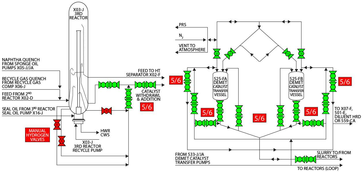
With respect to the ebulating bed with pumps that lift the reactor bed for processing heavy feedstock. A remote catalyst handling system having double and single seated ball valves prepares a fresh catalyst oil mixture which is continuously added through the reactor double-ball values into multi stage reactor trains in series. Via a separate pipeline, high pressure hydrogen is also continuously injected through metal seated ball valves into each reactor with the fresh catalyst. The hydrogen is consumed (i.e. that’s why the process is called reside “hydro” treating) and spent catalyst is withdrawn, via double ball valves. This controls the level of catalyst activity in the reactor enabling process to produce constant yields and product quality over time. This process increases the efficiency, effectiveness, and utilization to maximize the conversion of resid feedstocks to more valuable lower-boiling liquid products (i.e. lighter more valuable distillates) than can be refined downstream.
APPLICATION CHALLENGES: Coking buildup that increase operating torques and operational issues – optional purging systems can help prevent excessive buildup to reduce friction and allow the valve to be safely vented and drained of high pressure reactor effluent vapor and liquid.
WHAT TO LOOK FOR: When walking down a plant, look for the following to identify problems with existing valves:
- Packing leaks
- Body leaks
- Operations applying steam lances or barricades to avoid area
- Scaffolds
- VOC emission concerns from operations
- Fire precautions or scorched areas
HYDROGEN TESTING: When testing valves for leakage to atmosphere through leakage, ValvTechnologies meets ISO -15848-1 & 2 using helium for test medium. Valves see varying degrees of differential pressure. ValvTechnologies recommends and uses low pressure (60 psi) and working max ∆P, typically in the neighborhood of 3200 psi. The testing is performed with helium and zero-leakage is required for both ISO -15848-1 and ISO -15848-2 tests.Benefits of a ValvTechnologies’ Solution
- Pressure assisted sealing on fixed metal integral seat for positive shut off, true zero leak paths and no binding
- Ball and stem alignment with minimal packing wear and tear for extending packing life
- Advanced coating technologies
SAFETY CONCERNS: ValvTechnologies’ valves are proven to be effective in isolation (no leak through), have no body or packing leaks and do not bind like other product offerings .
THE VALVTECHNOLOGIES’ SOLUTION: Manufacturing a valve with zero leakage equals manufacturing a valve with a long, maintenance free life. In modern facility construction, major OEMs and EPC firms can be held responsible for the first 16,000 or more hours of operation. Poorly performing valves or valve failures can adversely affect the warranties and guaranties of the EPC/OEM firms and this liability can be many, many times costlier than the simple valve purchase price. Post warranty period, end users can experience unnecessary outage time costing them $100,000’s of dollars per day in lost production. ValvTechnologies has demonstrated this through long relationships with a leading, oil companies worldwide. Through mutually beneficial strategic supply contracts, customers buy and specifies ValvTechnologies’ products year over year because the products are proven to mitigate risk of poor performance and/or the need to make costly valve replacements within the warranty period for OEM/EPC firms or post warranty for end users.
TOTAL COST-OF-OWNERSHIP: Cost-of-ownership is low as evidenced by a recent Jan 2017 case study at a LC Finer where several originally installed single and double severe service ball values were service for the first time in double digit years. Additionally, heavy oil facility is pushing out planned valve outages due to outstanding on-going valve performance.
| DIFFERENTIATING FEATURES | |
Integral seat – safety of isolation
|
|
Highest spring strength in the category
|
|
Coatings/seating surface
|
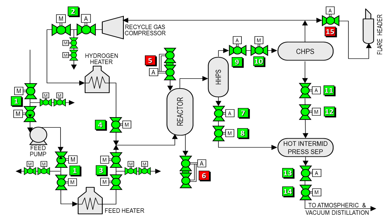
| FLOW DIAGRAM | |||||
|
|
|||||
| Item | Applications | Temp range (°F) | Pressure (psi) | Size (in) | |
| 1 | Feed isolation | 200 – 500 | 3200 | 8 – 12 | |
| 2 | Hydrogen heater inlet emergency block valve | 200 – 500 | 3200 | 8 – 12 | |
| 3 | Feed heater outlet emergency block valve | 500 – 800 | 3200 | 10 – 16 | |
| 4 | Hydrogen heater outlet emergency block valve | 500 – 800 | 3200 | 10 – 16 | |
| 5 | Reactor catalyst addition | 800 – 1000 | 3200 | 2 – 4 | |
| 6 | Reactor catalyst withdrawl | 800 – 1000 | 3200 | 2 – 4 | |
| 7 | Hot high pressure separator automated isolation | 800 – 900 | 3700 | 2 – 4 | |
| 8 | Hot high pressure separator manual isolation | 800 – 900 | 3700 | 2 – 4 | |
| 9 | Hot high pressure automated overhead vapor isolation | 800 – 900 | 3700 | 8 – 12 | |
| 10 | Hot high pressure manual overhead vapor isolation | 800 – 900 | 3700 | 8 – 12 | |
| 11 | Cold high pressure separator automated isolation | 200 | 1000 – 2600 | 3 – 10 | |
| 12 | Cold high pressure separator manual isolation | 200 | 1000 – 2600 | 3 – 10 | |
| 13 | Hot intermediate pressure separator automated isolation | 800 – 900 | 600 | 12 – 16 | |
| 14 | Hot intermediate pressure separator manual isolation | 800 – 900 | 600 | 12 – 16 | |
| 15 | Unit depressurization | 200 | 1000 – 2600 | 12 – 16 | |
