Standards Applicable to ValvTechnologies Valves for Power Plant Applications. ASME TDP-1, ASME B31.1 Boiler and ASME Pressure Vessel Code, Section I
General
|
| ASME B31.1 – 107.1 (C) |
Double block and bleed valves must have a way of releasing the fluid trapped between the two sealing components. |
| ASME B31.1 – 107.1 (D) |
Valves must have a blow-out proof stem. |
| ASME B31.1 – 107.3 |
End connections can be flanged, threaded or butt or socket welded. |
| ASME B31.1 – 107.4 |
Outside Screw and Yoke Stem Thread design shall be used for valves NPS 3 and larger for valves above 600psi pressure. |
| ASME B31.1 – 107.6 |
Valve bypasses shall be as per MSS SP-45 and at least schedule 80. |
| ASME Sect. I – PG-42.1 |
Valves shall meet the following ASME standards: ASME B16.5 Pipe glanges and flanged fittings.ASME B16.11 Forged Fittings, Socket-Welding and Threaded. ASME B16.20 Ring-Joint Gaskets and Grooves for Steel Pipe Flanges ASME B16.25 Buttwelding Ends ASME B16.34 Valves – Flanged, Threaded and Welding Ends |
| ASME Sect. I – PG-42.2 |
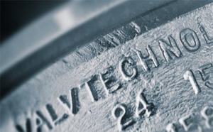
All valves and fittings shall be marked with name, manufacturers mark and primary service pressure rating |
| ASME Sect. I – PG-42.4.4 |
Special, limited and interpolated class valves are permitted. |
| ASME Sect. I – PG-42.4.7 |
Slip-on flanges shall not exceed NPS 4. |
| ASME Sect. I – PG-42.4.8 |
Socket-welded Flanges shall not exceed NPS 3 for Class 600 and lower and NPS 2 ½ for Class 900 and lower. |
Steam Stop Valve
|
| ASME B31.1 – 122.1.7 (A) |
All Boiler discharge outlets (except safety/relief valves or reheater connections) shall have a valve situated as near as practicably possible to the boiler nozzle. |
| ASME B31.1 – 122.1.7 (A.1) |
Boiler stop valves shall be bi-directional at design pressure. If pressure exceeds 150psi or temperature exceeds 366degF metal-to-metal seating must be used. |
| ASME B31.1 – 122.1.7 (A.1A) |
Each valve must be equipped with a visual position indicator. |
| ASME B31.1 – 122.1.7 (A.1B) |
Quarter turn valves must be fitted with a slow operating mechanism. |
| ASME B31.1 – 122.1.7 (A.2) |
Single Boiler/Prime Mover installations do not need a stop valve if the throttle valve is equipped with an open/close indicator. |
| ASME B31.1 – 122.1.7 (A.3) |
When several steam generators are connected to a common header the connection from each boiler having a manhole opening shall be fitted with two stop valves. The second stop valve have a pressure rating of at least 85% of the lowest set pressure of any safety valve on the boiler drum. |
| ASME B31.1 – 122.1.7 (A.4) |
All valves on steam lines shall have a pressure rating of at least 100psi. |
| ASME Sect. I – PG-58.3.1 |
Each connection to the boiler drum and superheater outlet header requires a Stop Valve. |
| ASME Sect. I – PG-58.3.2 |
When more than one boiler is connected to a common steam header the connection from each boiler (having a manhole cover) shall have two Stop Valve with a free-blow drain valve (a valve that discharges directly to atmosphere) connected between them. |
| ASME Sect. I – PG-59.5.1.1 |
If the shutoff valve is installed between the boiler and its superheater the safety valve capacity of the boiler shall meet PG-67.2 and PG-70, the superheater must be fitted with a safety valve as per PG-68.A Stop Valve is not required at the inlet or outlet of a reheater or separately fired boiler. |
| ASME Sect. I – PG-59.5.1.2 |
When Stop Valves are installed in the water-steam path between any two sections of a forced-flow steam generator with no fixed steam or waterline, the safety valves shall meet PG-67.4.4. |
| Feedwater Valves |
| ASME B31.1 – 122.1.7 (B.1) |
Except for high temperature water boilers and forced flow steam generators with no fixed steam and water line, boiler feedwater piping shall contain a check valve and stop valve.The stop valve shall be nearest the boiler and shall be ASME Class 250. |
| ASME B31.1 – 122.1.7 (B.2) |
The relative positions denoted above may be reversed on a single boiler-turbine installation. |
| ASME B31.1 – 122.1.7 (B.3) |
Each feed arrangement of a duplicate feed boiler shall meet these requirements. |
| ASME B31.1 – 122.1.7 (B.4) |
All connections of multiple branch feed supply line branch require stop and check valves, however the common source valves may be omitted. |
| ASME B31.1 – 122.1.7 (B.5) |
When two or more boilers are feed from a common source a regulating valve is required in each boiler supply line between the check valve and the supply source. |
| ASME B31.1 – 122.1.7 (B.6) |
Combination stop and check valves, with only one seat and seal are only allowed if used as a stop valve, with an additional check valve. |
| ASME B31.1 – 122.1.7 (B.7) |
Where a feedwater heating device is connected directly to the boiler without intervening valves, the feed valves and check valves shall be placed at the inlet of such device. |
| ASME B31.1 – 122.1.7 (B.8) |
The recirculating return line for a high temperature water boiler shall be provided with a stop valve and (optional) check valve.The stop valve shall be nearest to the boiler and |
| ASME B31.1 – 122.1.7 (B.9) |
A forced flow steam generator feed water piping may terminate after the stop valve providing a check valve (of a pressure rating equal to boiler inlet design pressure) is installed between the feed pump and the stop valve. |
| ASME Sect. I – PG-58.3.3 |
Feedwater piping requires a Stop Valve and a Check Valve. |
Boiler Drain Valves
|
| ASME B31.1 – 122.1.5 |
The drain valve shall not be smaller than the drain line. |
| ASME B31.1 – 122.1.5 (B) |
If drain valves are also intended for both drain and blowoff operations, require two valves that meet all general and blowoff valve requirements. |
| ASME B31.1 – 122.1.5 (C) |
A single drain valve is acceptable when the valve may be locked in the closed position or if a flanged connection is available downstream to accept a blank insert. |
| ASME Sect. I – PG-58.3.7 |
Two valves are required if the drain line is to be used for “blow-off” operation. |
| ASME Sect. I – PG-60.2.3 |
The water drain valve shall be fitted with a connection for a drain cock or valve to install a pipe of at least NPS 3/4” to a safe point of discharge. |
Safety, Relief & Safety-Relief Valves
|
| Safety Valves |
An automatic pressure-relieving device actuated by the static pressure upstream of the valve and characterized by full-opening pop action. It is used for gas or vapor service. |
| Relief Valves |
An automatic pressure relieving device actuated by the static pressure upstream of the valve which opens further with the increase in pressure over the opening pressure. |
| Safety-Relief Valves |
An automatic pressure-actuated relieving device suitable for use either as a safety valve or relief valve, depending on application. |
| ASME Sect. I – PG-67.1 |
All Boilers require at least one Safety or Safety-Relief Valve. Electric Boilers with power input of more than 1100 kw require at least two Safety or Safety-Relief Valves.All Boilers with more than 500 ft2 of bare tube water heating surface require at least two Safety or Safety-Relief Valves if the design steam generating capacity of the boiler exceeds 4000 lb/hr. |
| ASME Sect. I – PG-67.2 |
The Safety or Safety-Relief Valve shall have the ability to discharge all the steam generated by the boiler without the pressure rising more than 6% above either the highest set points of the safety valves or the boiler’s maximum allowable working pressure. |
| ASME Sect. I – PG-67.2.1 |
The Safety or Safety-Relief Valve capacity shall be more than the boiler’s maximum designed steaming capacity. |
| ASME Sect. I – PG-67.3 |
One or more Safety or Safety-Relief Valves shall be set at or below the boiler’s maximum allowable working pressure.Additional Safety or Safety-Relief Valves shall be set at less than 103% of the boiler’s maximum allowable working pressure. |
For saturated steam lines, the highest valve’s set pressure must be less than 110% the lowest valve’s set pressure (unless the valve is a Safety-Relief Valve on a high-temperature water boiler).ASME Sect. I – PG-67.5All safety valves or safety relief valves shall be so constructed that the failure of any part cannot obstruct the free and full discharge of steam and water from the valve.Safety valves or safety relief valves may be used that give any opening up to the full discharge capacity of the area of the opening of the inlet of the valve, provided the movement of the steam safety valve is such as not to induce lifting of water in the boiler. Deadweight or weighted lever safety valves or safety relief valves shall not be used. For high-temperature water boilers safety relief valves shall be used. Such valves shall be the closed bonnet type. In addition, the safety relief valves shall be capable of satisfactory operation when relieving water at the saturation temperature corresponding to the pressure at which the valve is set to blow.ASME Sect. I – PG-67.6A safety valve or safety relief valve over NPS 3 (DN 80), used for pressures greater than 15 psig (103 kPa), shall have a flanged or a weld-end inlet connection.ASME Sect. I – PG-67.7Safety valves or safety relief valves may have bronze parts. Such valves shall not be used on super-heaters delivering steam at a temperature over 450ºF (232ºC) and 306º F (152º C) respectively, and shall not be used for high-temperature water boilers.ASME Sect. I -PG-68.1Except as permitted in PG-58.3.1, every super-heater shall have one or more safety valves in the steam flow path between the super-heater outlet and the first stop valve.If the super-heater outlet header has a full, free steam passage from end to end and is so constructed that steam is supplied to it at practically equal intervals throughout its length so that there is a uniform flow of steam through the super-heater tubes and the header, the safety valve, or valves, may be located anywhere in the length of the headerASME Sect. I – PG-68.2The discharge capacity of the safety valve, or valves, on an attached super-heater may be included in determining the number and size of the safety valves for the boiler if there are no intervening valves between the super-heater safety valve and the boiler, and the discharge capacity of the safety valve, or valves, on the boiler, (not the super-heater) is at least 75% of the aggregate valve capacity required.ASME Sect. I – PG-68.3Every separately fired super-heater which may be shut off from the boiler and become a fired pressure vessel shall have one or more safety valves having a discharge capacity equal to 6 lb. of steam/hr./ft.2 of super-heater surface measured on the side exposed to the hot gases.ASME Sect. I – PG-68.4Every re-heater shall have one or more safety valves, such that the total relieving capacity is at least equal to the maximum steam flow for which the heater is designed.The capacity of the re-heater safety valves shall not be included in the required relieving capacity for the boiler and super-heater. One or more valves with a combined relief capacity not less than 15% of the required total shall be located along the steam flow path between the re-heater outlet and the first stop valve.ASME Sect. I – PG-68.6Each safety valve used on a super-heater or re-heater discharging superheated steam at a temperature over 450ºF (232ºC) shall have a casing, including the body, and bonnet (end cap) and spindle (stem), of steel, steel alloy, or equivalent heat-resisting material.The valve shall have a flanged inlet connection, or a weld-end inlet connection. It shall have the seat and disk of suitable heat erosive and corrosive resisting material.ASME Sect. I – PG-71.1When two or more safety valves are used on a boiler, they may be mounted either separately or as twin valves PG-71.1 When two or more safety valves are used on a boiler, they may be mounted either separately or as twin valves made by placing individual valves on Y-bases, or duplex valves having two valves in the same body casing.Twin valves made by placing individual valves on Y-bases, or duplex valves having two valves in the same body, shall be of approximately equal capacity. When not more than two valves of different sizes are mounted singly the relieving capacity of the smaller valve shall be not less than 50% of that of the larger valve.ASME Sect. I – PG-71.2The safety valve or safety relief valve or valves shall be connected to the boiler independent of any other connection, and attached as close as possible to the boiler or the normal steam flow path.Every safety valve or safety relief valves shall be connected so as to stand in an upright position, with spindle vertical. On high-temperature water boilers of the water-tube forced-circulation type, the valves shall be located at the boiler outlet.ASME Sect. I – PG-71.3The opening or connection between the boiler and the safety valve or safety relief valve shall have at least the area of the valve inlet.No valve of any description shall be placed between the required safety valve or safety relief valve or valves and the boiler, or on the discharge pipe between the safety valve or safety relief valve and the atmosphere. When a discharge pipe is used, the cross-sectional area shall be not less than the full rare of the valve outlet or of the total of the areas of the valve outlets, discharging there into. It shall be as short and straight as possible and so arranged as to avoid undue stresses on the valve or valves. All safety valve or safety relief valve discharges shall be so located or piped as to be carried clear from running boards or platforms. Ample provision for gravity drain shall be made in the discharge pipe at or near each safety valve or safety relief valve, and where water of condensation may collect. Each valve shall have an open gravity drain through the casing below the level of the valve seat. For iron-and steel-bodied valves exceeding NPS 2 ½ (DN 65), the drain hole shall be tapped not less than NPS 3/8 (DN 10). Discharge piping from safety relief valves on high-temperature water boilers shall be provided with adequate provisions for water drainage as well as the steam venting.ASME Sect. I – PG-71.4If a muffler (silencer) is used on a safety valve or safety relief valve; it shall have sufficient outlet area to prevent back pressure from interfering with the proper operation and discharge capacity of the valve.Mufflers shall not be used on high-temperature water boiler safety relief valves. When a safety valve or safety relief valve is exposed to outdoor elements which may affect operation of the valve, it is permissible to shield the valve with a satisfactory cover. The shield or cover shall be properly vented and arranged to permit servicing and normal operation of the valve.ASME Sect. I – PG-71.5When a boiler is fitted with two or more valves or safety relief valves on one connection, this connection to the boiler shall have a cross-sectional area not less than the combined areas of inlet connections of all the safety valves or safety relief valves with which it connects.ASME Sect. I – PG-71.7Every boiler shall have proper outlet connections for the required safety valve, or safety relief valve, or valves, independent of any other outside steam connection, the area of opening to be at least equal to the aggregate areas of inlet connections of all of the safety valves of safety relief valves to be attached.ASME Sect. I – PG-72.1Safety valves shall be designed and constructed to operate without chattering and attain full lift at a pressure not greater than 3% above the maximum pressure.After blowing down, all valves set at pressures of 375 psi (2600 kPa) or greater shall close at a pressure not lower than 96% of their set pressure, except that all drum valves installed on a single boiler may be set to reseat at a pressure not lower than 96% of the set pressure of the lowest set drum valve. All valves set at pressures below 375 psi (2600 kPa) shall have a blowdown not greater than that specified in the following table, except that all drum valves installed on a single boiler may be set to reseat at a pressure not lower than the reseating pressure of the lowest set drum valve: Set Pressure (psi) Maximum Blowdown =67 and =250 6% set pressure >250 15psi The minimum blowdown for all safety or safety relief valves shall be 2 psi (13.8 kPa) or 2% of the set pressure, whichever is greater. Safety valves used on forced-flow steam generators with no fixed steam and waterline, and safety relief with no fixed steam and waterline, and safety relief valves used on high-temperature water boilers may be set and adjusted to close after blowing down not more than 10% of the set pressure.ASME Sect. I – PG-72.2The popping point tolerance plus or minus shall not exceed that specified in the following table:
| Set Pressure (psi) |
|
Tolerance from Set Pressure |
| =70 |
|
2 psi |
| >70 and =300 |
|
3% set pressure |
| >300 and =1000 |
|
10psi |
| >1000 |
|
1% set pressure |
ASME Sect. I -PG-73.1.7Valves having screwed inlet or outlet connections shall be provided with wrenching surfaces to allow for normal installation without damaging operating parts.ASME Sect. I – PG-73.2.1Cast iron seats and disks (i.e. endcap/integral seat and internals) are not permitted.ASME Sect. I – PG-73.2.2Springs of corrosion resistant material or having a corrosion resistant coating are required.The seats and disks of safety valves or safety relief valves shall be of suitable material to resist corrosion by the media.ASME Sect. I – PG-73.2.3Materials used in bodies and bonnets or yokes shall be listed in Section II, Parts A and B, and identified in Tables 1A and 1B of Section II, Part D, as permitted for Section I construction.Internal components shall be constructed from materials:
- listed in ASME Section II
- listed in ASTM Specifications
ASME Sect. I – PG-73.4.1Valves exceeding 1 in. (DN 25) inlet size or 300 psig (2070 kPa) set pressure shall meet the following requirements:
- Primary pressure containing cast and welded parts of pressure relief valves shall be tested at a pressure at 1.5 times the design pressure of the parts.
- These tests shall be conducted after all machining operations to the parts have been completed.
- There shall be no visible signs of leakage
ASME Sect. I – PG-73.4.2Every valve shall be tested with steam by the manufacturer or assembler to demonstrate the popping point, blowdown, tightness, and pressure containing integrity.Valves beyond the capability of production test facilities may be shop tested with air, provided required field tested and applicable adjustments are made.ASME Sect. I – PG-110Stamping of Safety Valves: Each safety valve shall be plainly marked with the required data by the Manufacturer or Assembler (see PG-73.3.4) in such a way that the marking will not be obliterated in service.The marking shall be placed on the valve or on a nameplate securely fastened to the valve. The Code “V” symbol shall be stamped on the valves or nameplate by the Manufacturer or Assembler, as applicable. The other required data may be stamped, etched, impressed, or cast on the valve or nameplate. The marking shall include the following:
- the name (or an acceptable abbreviation) of the Manufacturer or Assembler, as applicable;
- Manufacturer’s design or type number;
- NPS (the nominal pipe size of the valve inlet);
- set pressure_____psi (kPa);
- capacity¬______lb/hr (kg/hr) (in accordance with PG-67.5 and with the valve adjusted for the blowdown permitted by PG-72);
- year built, or alternatively, a coding may be marked on the valve such that the valve Manufacturer or Assembler can identify the year the valve was assembled and tested;
- ASME ‘V’ symbol.
Power-Actuated Pressure Relieving Valve
|
| Power-Actuated Pressure Relieving Valve |
A Safety, Relief or Safety-Relief Valve whose movements to open or close are fully controlled by a power source.The valve may discharge to atmosphere or a lower pressure container. The effect of downstream conditions on the valve’s discharge capacity must be taken into account.The over-pressure signal to the Power-Actuated Pressure Relieving Valves shall override all other signals.nstall a pipe of at least NPS 3/4” to a safe point of discharge. |
| ASME Sect. I – PG-67.4.1 |
For automatically controlled Forced-Flow Steam Generators with no fixed steam or waterline, one or more Power-Actuated Pressure Relieving Valves, that receive a control signal to open when the maximum allowable working pressure at the superheater is exceeded, may also be used.The total combined Power-Actuated Pressure Relieving Valve capacity shall be more than 10% the maximum design steaming capacity of the boiler.An isolating outside-screw-and-yoke or ball valve may be installed between the boiler and Power-Actuated Pressure Relieving Valve if a same capacity “redundant” Power-Actuated Pressure Relieving Valve is also installed to the boiler.The Isolation Valve port area shall by the same or greater than that of the Power-Actuated Pressure Relieving Valve’s inlet.Ball type Power-Actuated Pressure Relieving Isolation Valves must include a method of identifying if the valve is open or closed.If the Isolation Valve is power actuated a manual override mechanism must be provided. Power-Actuated Pressure Relieving Valves discharging intermediate pressure and incorporated into the start-up/bypass systems of the boiler do not need to be capacity certified, but shall be marked, with the capacity rating by the valve manufacturer. |
| ASME Sect. I – PG-67.4.2 |
The combined spring-loaded safety valves and power-actuated pressure relieving capacity (installed under PG-67.4.1), shall be more than 100% of the max. designed steaming capacity of the boiler.Less than 30% of the total relieving capacity shall be allowed for the power-actuated pressure relieving valves.Any or all of the spring-loaded safety valves may be set above the maximum allowable working pressure of the parts to which they are connected, but the set pressures shall be such that when all of these valves (together with the power-actuated pressure relieving valves) are in operation the pressure will not rise more than 20% above the maximum allowable working pressure of any part of the boiler, except for the steam piping between the boiler and the prime mover. |
| ASME Sect. I – PG-67.4.4 |
When stop valves are installed in the water-stream flow path between any two sections of a forced-flow steam generator with no fixed steam and waterline the following shall apply: |
| ASME Sect. I – PG-67.4.4.1 |
The power-actuated pressure relieving valves(s) required by PG-67.4.1 shall also receive a control impulse to open when the maximum allowable working pressure of the component, having the lowest pressure level upstream to the stop valve, is exceeded. |
| ASME Sect. I – PG-67.4.4.2 |
The spring-loaded safety valves shall be located to provide the pressure protection requirements in PG-67.4.2 or PG-64.3. |
Blowoff & Blowdown Valves
|
| Blowoff Valves |
Valves connected to the boiler which water may be blown out intermittently under pressure, to remove accumulated sediment from equipment and/or piping, or to lower water level in a rapid manner. |
| Blowdown Valves |
Valve connected to the boiler which water may be continuously blown out under pressure, to control the concentration of dissolved solids in the boiler water.pment and/or piping, or to lower water level in a rapid manner. |
| ASME B31.1 – 122.1.7 (C.1) |
Valves with pockets where sediment may build up are prohibited. lower water level in a rapid manner. |
| ASME B31.1 – 122.1.7 (C.3) |
The pipe between the boiler and the blowoff valves shall be the same size as the boiler connection (however it may be larger for the return of condensate). |
| ASME B31.1 – 122.1.7 (C.4) |
For all boilers exceeding normal water content of 100 gal or a working pressure of 100psi, each bottom blowoff pipe shall have two slow-opening valves or one quick opening valve at the boiler nozzle followed by a slow-opening valve. |
| ASME B31.1 – 122.1.7 (C.5/6) |
If the required design pressure of the valve (either 125% of the working pressure of the boiler or the working pressure plus 225psi, but never less than 100psi) is greater than 250psi, the valves shall be of steel, ASME Class 300 construction. If the design pressure is less than 250psi the valve must be of bronze, cast iron, ductile iron, or steel, ASME Class 250. Cast iron blowoff valves shall not exceed 2 ½” NPS. |
| ASME B31.1 – 122.1.7 (C.8) |
A slow-opening valve is defined as one which requires at least five 360 degree turns of the operating mechanism to change from fully closed to fully open. |
| ASME B31.1 – 122.1.7 (C.9) |
If the boiler has several blowoff pipes, the slow-opening valve may be placed on the masterline or on each blowoff line. |
| ASME B31.1 – 122.1.7 (C.10) |
The two required blowoff valves may be combined in one body, provided they are the equivalent of two slow-opening valves or one quick and one slow opening valve and that the failure of one will not affect the operation of the other. |
| ASME B31.1 – 122.1.7 (C.11) |
Traction or portable boilers only need one (quick or slow opening) blowoff valve. of the other. |
| ASME B31.1 – 122.1.7 (C.12) |
Boilers with normal water content of 100 gal or less require only a single slow-opening blowoff valve. |
| Miscellaneous Valves |
| ASME Sect. I – PG-60.3.4 |
The boiler to remote level indicator connection valve shall be at least NPS ¾. |
| ASME Sect. I – PG-60.3.7 |
Stop Valves in the connections between the boiler and water column or boiler and gauge glass must be of through-flow construction and have indication whether it is open or closed. |
Main, Cold Reheat and Hot Reheat Steam Drains: Superheater Attemporator
|
| ASME TDP-1 3.3 Main Steam Drains |
All branches going into the turbine should be reviewed for low points. Main steam piping drains should not be manifolded together with any other drains from the boiler. All drain lines and drain pots, including connections before the turbine stop valve, should have a minimum I.D. of 1 inch. At least one valve in each line should be power operated. Manual valves installed in series (typically upstream) should be locked open.The minimum diameter before and after seat drains is ¾ inch. Similarly, drains between the main steam stop valve and first stage nozzles, after-seat drains on the main steam stop valve, before- and after-seat drains on the control or admission valves and low point drains on any of the main steam piping downstream of the control valves, should also have minimum flow passageways of ¾ inch |
| ASME TDP-1 3.6 Hot Reheat Steam Drains |
Hot Reheat Piping. The hot reheat piping to condensers should have a minimum connection of 4 inch, 9 inch long, reducing to a minimum of a 1-1/2 NPS. At least one full ported power-operated drain valve should be located in the smaller line (minimum 1-1/2 inch). Any additional manual valves must be locked open. |
| ASME TDP-1 3.4 Cold Reheat Steam Drains |
Cold Reheat Piping. The recommended system is a design to provide a signal to permit operator action to stop water inflow. A drain pot at the low point of each cold reheat line fabricated from a minimum of a 6” pipe. Each pot shall have 2” full port drain lines, a minimum of one 2” full port power-operated valve is required. Where possible, the valve should be fail open. |
| ASME TDP-1 3.4 Superheat Attemperator |
Superheat Attemperator. A power-operated block valve should override all manual signals and close when the control valve is closed. |
| ASME TDP-1 Overview |
| ASME TDP-1 3.1.2 Overview |
Once-through flow units, because of their start up systems, offer a greater potential for water induction through the main steam system, during start-up and shutdown operating modes. |
| ASME TDP-1 3.7 |
A major cause of water induction into turbines has been from extraction systems, feedwater systems and associated drains. Two independent means of automatically preventing water damage should be provided. In general, there are three options: a) Water flowing from the ruptured tubes (four open ends). b) Water equivalent to 10% of the tube side flow.A power operated drain valve with control room indication should be located in low points of extraction pipe between the turbine and block valve. The drain should be routed separately to the condenser.No bypasses should be around extraction steam block or check valves. |

