Hydrotreating – Application Overview
Hydrotreating is the process of removal of contaminants like sulfur, nitrogen and metals from refined petroleum products and to saturate olefins and aromatics to produce a clean product for further processing or finished product sales.
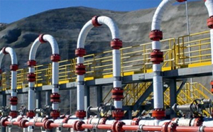
The process involves the liquid feed being mixed with hydrogen, fed into a heater and then the heated mix fed into a fixed bed catalytic reactor vessel. Feed and hydrogen pass downward in a hydrogenation reactor packed with various types of catalyst. The effluent is cooled and liquid hydrocarbons are separated from the hydrogen/hydrogen sulphide/ammonia gas. Acid gases are absorbed from the hydrogen in the amine scrubber.
Further separation of liquefied petroleum gas (LPG) gases occurs in the low pressure separator prior to sending the hydrocarbon liquids to fractionation for product separation.
HYDROTREATING BED DESIGNS
There are three types of hydrotreating bed designs: fixed, moving and fluidized.
- Fixed bed hydrotreating is a licensed process using guard reactors to prevent poisoning of the catalyst.
- The process stream down-flows over a bed of catalyst pellets that are held in place and do not move
- The guard reactor catalyst must be frequently removed due to its collection of heavy metals. Two licensors have developed methods of loading the guard reactors with fresh catalyst without taking the unit off-line.
- Zero leakage catalyst addition and withdrawal isolation valves are critical to the proper functioning of this process.
In a moving bed reactor, a continuous fresh catalyst renewal is added at the reactor top, and spent catalyst is withdrawn at the bottom.
In a fluidized bed reactor, the process stream up-flows through catalyst pellets at high enough velocities to suspend the catalyst, causing it to behave as though it were a fluid.
An ebullating bed is a type of fluidized bed, with continuous catalyst addition and withdrawal capability.
HYDROTREATING PROCESSES
Naphtha hydrotreating: Naphtha feed comes from crude oil distillation or from delayed coking and visbreaking. These non-severe service light oils are cleaned and fed to the reformer.
FCC feed hydrotreating: heavy gas oil feeds from atmospheric, vacuum, coking, visbreaking and solvent deasphalting, are catalytically converted to gas/LPG, gasoline, light cycle oil, slurry oil and coke. Nitrogen is removed for better FCC catalyst activity and sulfur removal for SOx reduction in the flue gas and easier post-FCC treatment
Distillate hydrotreating: feed comes from crude oil distillation and fluid catalytic cracking processes. Outputs are mainly diesel and jet fuel.
PROCESS OBJECTIVE
To remove contaminants (sulfur, nitrogen, metals) and saturate olefins and aromatics to produce a clean product for further processing or finished product sales.
PRIMARY PROCESS TECHNIQUE
Hydrogenation occurs in a fixed catalyst bed to improve H/C ratios and to remove sulfur, nitrogen and metals.
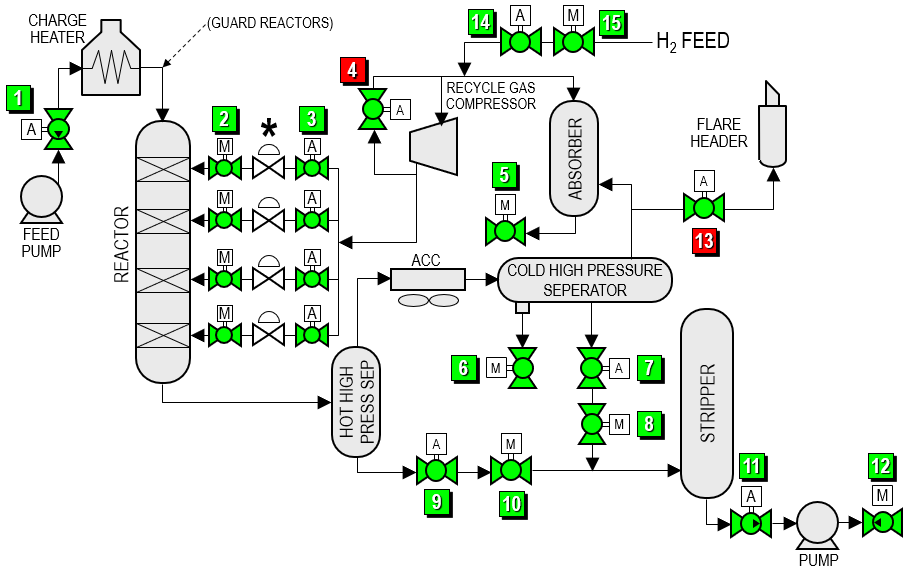
| FLOW DIAGRAM | |||||
 |
|||||
| Item | Applications | Temp range (°F) | Pressure (psi) | Size (in) | |
| 1 | Feed pump isolation | 400 – 600 | 3200 | 8 – 12 | |
| 2 | H2 automated inlet isolation | 150 – 200 | 2000 – 3000 | 2 – 6 | |
| 3 | H2 manual inlet isolation | 150 – 200 | 2000 – 3000 | 2 – 6 | |
| 4 | Recycle gas compressor surge | 150 – 200 | 2000 – 3000 | 4 – 8 | |
| 5 | Rich amine isolation | 200 | 2000 – 3000 | 4 – 10 | |
| 6 | Sour water isolation | 200 | 3200 | 2 – 6 | |
| 7 | Cold high pressure separator automated level control isolation | 200 | 2200 | 1 | |
| 8 | Cold high pressure separator manual level control isolation | 200 | 2200 | 1 | |
| 9 | Hot high pressure separator automated level control isolation | 800 – 900 | 2600 | 1 | |
| 10 | Hot high pressure separator manual level control isolation | 800 – 900 | 2600 | 1 | |
| 11 | Stripper bottoms emergency block valve | 350 – 500 | 50 | 8 – 12 | |
| 12 | Stripper bottoms pump isolation | 350 – 500 | 150 | 6 – 10 | |
| 13 | Stripper bottoms pump isolation | 200 |
2200 | 6 – 10 | |
| 14 | H2 automated feed isolation | 200 |
1500 | 2 – 6 | |
| 15 | H2 manual feed isolation | 200 |
1500 | 2 – 6 | |