Naphtha Hydrotreating – Application Overview
Naphtha feed comes from crude oil distillation or from delayed coking and visbreaking. It is cleaned and fed to the reformer.
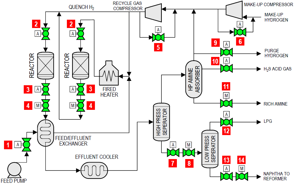
| FLOW DIAGRAM | |||||
 |
|||||
| Item | Applications | Temp range (°F) | Pressure (psi) | Size (in) | |
| 1 | Feed pump isolation valve | 200 – 320 | 1200 – 1300 | 8 – 12 | |
| 2 | Reactor isolation / catalyst addition | 400 – 550 | 1100 – 1200 | 4 – 12 | |
| 3 | Manual reactor unloading isolation | 400 – 550 | 1000 – 1100 | 4 – 12 | |
| 4 | Automatic reactor unloading isolation | 400 – 550 | 1000 – 1100 | 4 – 12 | |
| 5 | Recycle gas compressor surge | 120 | 1200 – 1300 | 4 – 8 | |
| 6 | Make-up compressor surge | 120 | 950 – 1050 | 4 – 8 | |
| 7 | High-pressure separator automated level control isolation | 250 | 1000 | 6 – 10 | |
| 8 | High-pressure separator letdown manual level control isolation | 250 | 1000 | 6 – 10 | |
| 9 | Purge hydrogen emergency block valve | 250 | 1000 | 1 – 8 | |
| 10 | H2S emergency block valve | 250 | 1000 | 1 – 8 | |
| 11 | Rich amine isolation | 250 | 1000 | 4 – 10 | |
| 12 | LPG emergency block valve | 250 | 300 – 800 | 1 – 8 | |
| 13 | Low-pressure separator automated level control isolation | 250 | 300 – 800 | 6 – 10 | |
| 14 | Low-pressure separator letdown manual level control isolation | 250 | 300 – 800 | 6 – 10 | |