Continuous Catalytic Reforming (CCR) – Application Overview
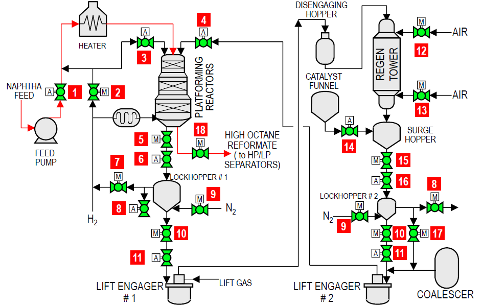
Reforming is used to convert low-octane naphtha into a high-octane reformate for petrol blending and to provide aromatics for petrochemical plants. It also produces high purity hydrogen for hydrotreating processes.
| FLOW DIAGRAM | |||||
 |
|||||
| Item | Applications | Temp range (°F) | Pressure (psi) | Size (in) | |
| 1 | Feed pump isolation valve | 200 – 550 | 300 – 800 | 6 – 10 | |
| 2 | Automated reactor overhead regeneration | 200 – 550 | 300 – 800 | 1 – 8 | |
| 3 | Automated reactor overhead purge | 200 – 550 | 300 – 800 | 1 – 8 | |
| 4 | Manual standby reduction zone purge | 200 – 550 | 300 – 800 | 1 – 8 | |
| 5 | Manual reactor bottoms unloading valve | 200 – 550 | 300 – 800 | 1 – 8 | |
| 6 | Automated reactor bottoms unloading valve | 200 – 550 | 300 – 800 | 1 – 8 | |
| 7 | Manual hydrogen loading to lock hopper #1 | 200 – 400 | 300 – 700 | 1 – 8 | |
| 8 | Manual hydrogen vent to lock hopper #1 & 2 | 200 – 400 | 300 – 700 | 1 – 8 | |
| 9 | Manual nitrogen purge for lock hopper #1 & 2 | 200 – 400 | 300 – 700 | 1 – 8 | |
| 10 | Manual catalyst for lift engager 1 & 2 | 200 – 400 | 300 – 700 | 1 – 8 | |
| 11 | Automated catalyst for lift engager 1 & 2 | 200 – 400 | 300 – 700 | 1 – 8 | |
| 12 | Manual air valve to regeneration cooler | 200 – 400 | 300 – 700 | 6 | |
| 13 | Manual air valve to surge hopper | 200 – 400 | 300 – 700 | 6 | |
| 14 | Automated fresh catalyst addition | 100 – 150 | 300 – 500 | 2 – 8 | |
| 15 | Manual regen catalyst uploading from surge hopper | 200 – 400 | 300 – 700 | 6 | |
| 16 | Manual regen catalyst uploading from surge hopper | 200 – 400 | 300 – 700 | 6 | |
| 17 | Manual pressure balancing for lock hopper | 200 – 400 | 300 – 700 | 6 | |
| 18 | Manual reactor reformate isolation valve | 200 – 400 | 300 – 700 | 6 – 10 | |