Fixed Bed Hydrotreating – Application Overview
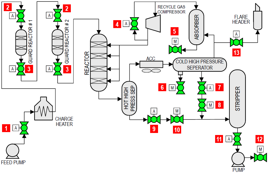
This is a licensed process using guard reactors to prevent poisoning of the catalyst. Zero leak catalyst addition and withdrawal isolation valves are critical to the proper functioning of this process.
| FLOW DIAGRAM | |||||
 |
|||||
| Item | Applications | Temp range (°F) | Pressure (psi) | Size (in) | |
| 1 | Feed pump isolation | 200 – 320 | 3200 | 8 – 12 | |
| 2 | Guard reactor isolation / catalyst addition | 400 – 550 | 3200 | 4 – 12 | |
| 3 | Guard reactor isolation / catalyst withdrawal | 400 – 550 | 3200 | 4 – 12 | |
| 4 | Recycle gas compressor surge | 50 – 100 | 2000 – 3000 | 4 – 8 | |
| 5 | Rich amine isolation | 100 | 2000 – 3000 | 4 – 10 | |
| 6 | Sour water isolation | 100 | 3200 | 2 – 6 | |
| 7 | Cold high-pressure separator automated level control isolation | 100 | 2200 | 6 – 10 | |
| 8 | Cold high-pressure separator manual level control Isolation | 100 | 2200 | 6 – 10 | |
| 9 | Hot high-pressure separator automated level control isolation | 400 – 500 | 2600 | 8 – 12 | |
| 10 | Hot high-pressure separator manual level control isolation | 400 – 500 | 2600 | 8 – 12 | |
| 11 | Stripper bottoms emergency block valve | 250 – 450 | 50 | 8 – 12 | |
| 12 | Stripper bottoms pump isolation | 250 – 450 | 150 | 6 – 10 | |
| 13 | Unit depressurization | 100 | 2200 | 6 – 10 | |