Gasification – Application Overview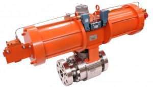
Gasification is a thermal/chemical process that converts any carbon-containing material into a synthesis gas composed primarily of carbon monoxide and hydrogen. During this process, a lower-value carbonaceous/hydrocarbon feedstock (coal, petroleum coke, biomass, etc.) is subjected to high temperatures, moderate pressures and reducing conditions, for conversion to a higher value synthesis gas (syngas) by means of partial oxidation with air, oxygen, and/or steam.
The hydrogen-to-carbon ratio of coal is lower than that of liquid or gaseous fuels. Therefore conversion of coal into an alternative fuel must involve either an addition of hydrogen or a rejection of carbon.
Gasification converts low value residuals into higher value synthetic products. Petroleum feed is mixed at high temperatures (above 350°C/662°F) with oxygen and steam in a gasifier vessel. A hydrogen and carbon monoxide gas mixture called synthesis gas (syngas) fuel is produced and drawn from the gasifier.
The syngas is further scrubbed and cleaned. An inter ash/slag by-product is also produced at the bottom of the gasifier.
PROCESS BENEFITS:
Fuel flexible
- Coal, pet coke, refinery wastes, biomass, sewage sludge and MSW
- High sulfur feeds accepted
Environmentally superior
- Low CO, SOx and NOx emissions
- Zero particulate emissions
- No solid wastes
- Sulfur recovered as by-product
PROCESS:
- A hydrocarbon feedstock is fed into a high-pressure, high-temperature chemical reactor (gasifier) containing steam and a limited amount of oxygen.
- Under these ‘reducing’ conditions, the chemical bonds in the feedstock are severed by the extreme heat and pressure and a syngas is formed and drawn from the gasifier.
- The moisture in the feedstock is evaporated and exits the gasifier in the vapor phase as a component of the gas stream, acting as a diluent, thereby reducing the energy content of the gas.
- Under the reducing conditions in the gasifier, most of the fuel’s sulfur converts to hydrogen sulfide (H2S).
- The syngas is further scrubbed/cleaned.
- An inert ash/slag by-product is also produced at the bottom of the gasifier.
MARKET APPLICATIONS:
- Refinery based co-production (power, steam, hydrogen) from coke, resid.
- Baseload power
- Coal repowering
- Combined cycle refueling
- Feed to chemicals – NH3/urea
- Feed to methanol
- Feed to ultra-clean fuel (diesel)
DRIVERS:
- Electric power deregulation
- Increased energy demand
- Clean energy solutions – greenhouse gas reductions
- Strain on natural gas – driving prices up – supply uncertainty
- Continued reliance on coal in U.S.
- Significant reserves – clean coal emphasis
- Significant world scale coking capacity additions – more pet coke on the market
- Refineries processing heavier crudes – results in lower value pet coke
- Increased demand for hydrogen in refineries
- Ultra clean transportation fuel
- Direct reduced iron production
- Chemicals – ammonia / fertilizers
ENVIRONMENTAL BENEFITS:
- Gasification processes “bad actors” in coal/coke prior to end use
- Allows power generation of low value fuels (feeds) with near natural gas performance and emissions
- Lower all around emissions versus conventional solid fuel technologies
SUMMARY:
- Gasification is the cleanest, most efficient commercial means to generate power from solid fuels
- Continuing trend of oil, gas and electric power markets improves IGCC prospects
- Growth rate of gasification is accelerating – additional opportunities in chemicals (from coal and petcoke)
- Environmental pressures (including Hg, CO2) favor gasification
- Technical advancements aid gasification
- Challenge – providing the market a mature technology
- This industry represents a ripe market for specialty valve OEMs due to combination of technology, plant size and market growth
| DIFFERENTIATING FEATURES | |
Integral seat – safety of isolation
|
|
Highest spring strength in the category
|
|
Coatings/seating surface
|
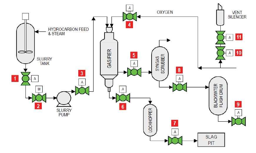
| FLOW DIAGRAM | |||||
 |
|||||
| Item | Applications | Temp range (°F) | Pressure (psi) | Size (in) | |
| 1 | Slurry tank emergency block valve | 250 – 500 | 100 – 200 | 6 – 10 | |
| 2 | Feed slurry pump isolation | 38 – 100 | 100 – 200 | 6 – 10 | |
| 3 | Gasifier isolation | 38 – 150 | 900 – 1200 | 6 – 10 | |
| 4 | Oxygen feed isolation | 38 – 100 | 900 – 1200 | 4 – 8 | |
| 5 | Coarse slag lock hopper isolation | 50 – 350 | 900 – 1200 | 6 – 12 | |
| 6 | Lock hopper drum inlet | 200 – 320 | 900 – 1200 | 12 – 24 | |
| 7 | Lock hopper drum outlet | 200 – 320 | 900 – 1200 | 12 – 24 | |
| 8 | Level control let down isolation | 38 – 150 | 100 – 200 | 4 – 10 | |
| 9 | Backwater flash drum isolation | 50 – 350 | 900 – 1200 | 4 – 10 | |
| 10 | Oxygen depressurizing valve | 38 – 100 | 900 – 1200 | 4 – 8 | |
| 11 | Oxygen depressurizing isolation | 38 – 100 | 900 – 1200– 2600 | 4 – 8 | |