Hydrocracking – Application Overview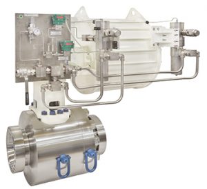
Hydrocracking is a catalytic cracking process assisted by the presence of an elevated partial pressure of hydrogen gas. It is used for feedstock that are difficult to process either by catalytic cracking or reforming. Like hydrotreating, hydrogen is used to purify the hydrocarbon stream from sulfur and nitrogen hetero-atoms. Hydrogen also reduces tar formation and prevents build-up of coke on the catalyst. Hydrogen converts sulfur and nitrogen compounds present into H2S and ammonia.
The process employs high-pressures (1000-2000 psi), high-temperature (400-850 °C), a catalyst and hydrogen.
The main products from hydrocracking are jet fuel, diesel, high octane petrol fractions and LPG with very low sulfur and other contaminant content.
Hydrocracking produces low sulfur fuels, desulfurisation, denitrogenation, demetallization. Cracking of aromatic bonds. Feedstock for FCC units for valuable products. Hydrocrackers are typically straight run units with turn around period of 36/48/60 months depending on the refinery unit needs and configurations.
CRACKING METHODS
“Cracking” breaks larger molecules into smaller ones, through thermic or catalytic method.
Thermal: large hydrocarbon molecules are heated at high temperatures (sometimes high pressures as well) until they break apart.
Steam: high temperature steam at 1500°F (816°C) is used to break ethane, butane and naphtha into ethylene and benzene, which are used to manufacture chemicals.
Catalytic: uses a catalyst to speed up the cracking reaction. Catalysts include zeolite, aluminum hydrosilicate, bauxite and silica-alumina.
FCC fluid catalytic cracking: a hot, fluid catalyst at 1000°F (538°C) cracks heavy gas oil into gas oils and gasoline.
Hydrocracking: similar to fluid catalytic cracking, but uses a different catalyst, lower temperatures, higher pressure and hydrogen gas. It cracks heavy oil into gasoline and kerosene (jet fuel).
Visbreaking: residual from the distillation tower is heated 900°F (482°C), cooled with gas oil and rapidly burned (flashed) in a distillation tower. This process reduces the viscosity of heavy weight oils and produces tar.
Coking: residual from the distillation tower is heated to temperatures above 900°F (482°C) until it cracks into heavy oil, gasoline and naphtha. When the process is done, a heavy, almost pure carbon residue is left (coke); the coke is cleaned from the cokers and disposed.
PROCESS OBJECTIVE
To remove feed contaminants (sulfur, nitrogen, metals) and to convert low value gas oils to valuable products (naphtha, middle distillates, and ultra-clean lube base stocks).
PRIMARY PROCESS TECHNIQUE
Hydrogenation occurs in fixed hydrotreating catalyst beds to improve H/C ratios and to remove sulfur, nitrogen, and metals. This is followed by one or more reactors with fixed hydrocracking catalyst beds to dealkylate aromatic rings, open naphthene rings and hydrocrack paraffin chains.
APPLICATION CHALLENGES
Hydrocracking requires dependable isolation. Global practice is to purchase valves based on certain standards and guidelines, however, these standards do not ensure or guarantee dependable isolation when required. As a consequence, valves fail unexpectedly during operations, leading to shut downs and huge expenses. (ex: a typical hydrocracker production loss can cost $1 – $1.5 million per day, not including associated costs like scaffolding, spares, deployment of personnel, spare parts, repair costs extra, etc.
Particular to hydrocrackers, a lot of rich hydrogen is used along with expensive catalysts in high-temperature and pressure: to manitain plant safety, it is very important to ensure there is no internal or external leakage out of the isolation valves.
RECOMMENDED PRODUCT(S)
- The majority of valves in hydrocracking and hydrotreating require V Series products; NexTech® is another competitive alternative.
- Typically 2 – 18” sizes and pressure class 300# – #2500, typically A105, 316/ 316H, 304H, 321/321H, 347H (rarely).
WHY THE VALVTECHNOLOGIES’ SOLUTION
Margins seen at refineries are directly impacted when plants shut down due to failure of critical valves and key reliability process control equipment. ValvTechnologies’ products are specially designed to meet, if not exceed, refinery requirements to prevent unplanned outages.
ValvTechnologies offer zero-leakage at all operating conditions and also low FE in accordance with ISO-15848-1 min. Class B with our packing designs.
BENEFITS OF VALVTECHNOLOGIES’ SOLUTION
- Process safety
- Increase optimization and utilization rates
- Operational efficiency
- Higher throughput
- Lower total cost-of-ownership
- Reliability and yield improvements
- Mechanical availability (MTBF)
| DIFFERENTIATING FEATURES | |
Zero-leakage
|
|
Low emissions
|
|
Coatings/seating surface
|
|
Best certifications
|
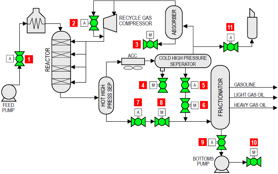
| FLOW DIAGRAM | |||||
|
|
|||||
| Item | Applications | Temp range (°F) | Pressure (psi) | Size (in) | |
| 1 | Feed pump isolation valves | 100 – 300 | 3200 | 8 – 12 | |
| 2 | Recycle gas compressor surge | 50 – 100 | 2000 – 3000 | 4 – 8 | |
| 3 | Rich amine isolation | 100 | 2000 – 3000 | 4 – 10 | |
| 4 | Sour water isolation | 100 | 2200 | 2 – 6 | |
| 5 | Cold high-pressure separator automated level control isolation | 100 | 2200 | 6 – 10 | |
| 6 | Cold high-pressure separator manual level control isolation | 100 | 2200 | 6 – 10 | |
| 7 | Hot high-pressure separator automated level control isolation | 400 – 500 | 2600 | 8 – 12 | |
| 8 | Hot high-pressure separator manual level control isolation | 400 – 500 | 2600 | 8 – 12 | |
| 9 | Frac bottoms emergency block valve | 250 – 550 | 50 | 8 – 12 | |
| 10 | Frac bottoms pump isolation | 250 – 550 | 150 | 6 – 10 | |
| 11 | Unit depressurization | 100 | 2200 | 6 – 10 | |